Overview
In the Mechanical Design Project course (4GC10) at TU Eindhoven, our small team designed and built a Precision Kinematic Mounting (PKM) system for steering a mirror in a LASER communication satellite. The mechanism needed to achieve high-precision beam alignment using only mechanical adjustments — no electronics or motors — through flexure-based transmission with fine-tuning capability.
Design Concept
The system consists of three modular assemblies:
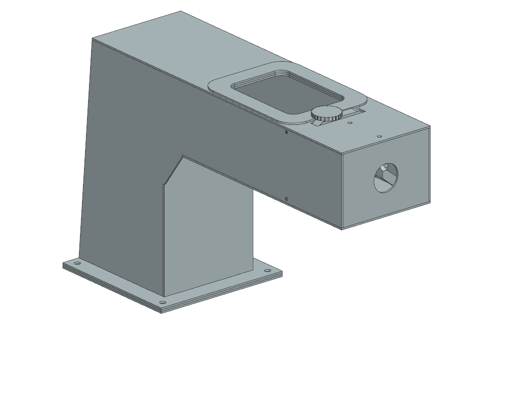
- Structure — A 150 mm x 400 mm x 240 mm enclosure with laser-cut faces glued at edges, featuring a maintenance access hole with doubler plates for stiffness retention
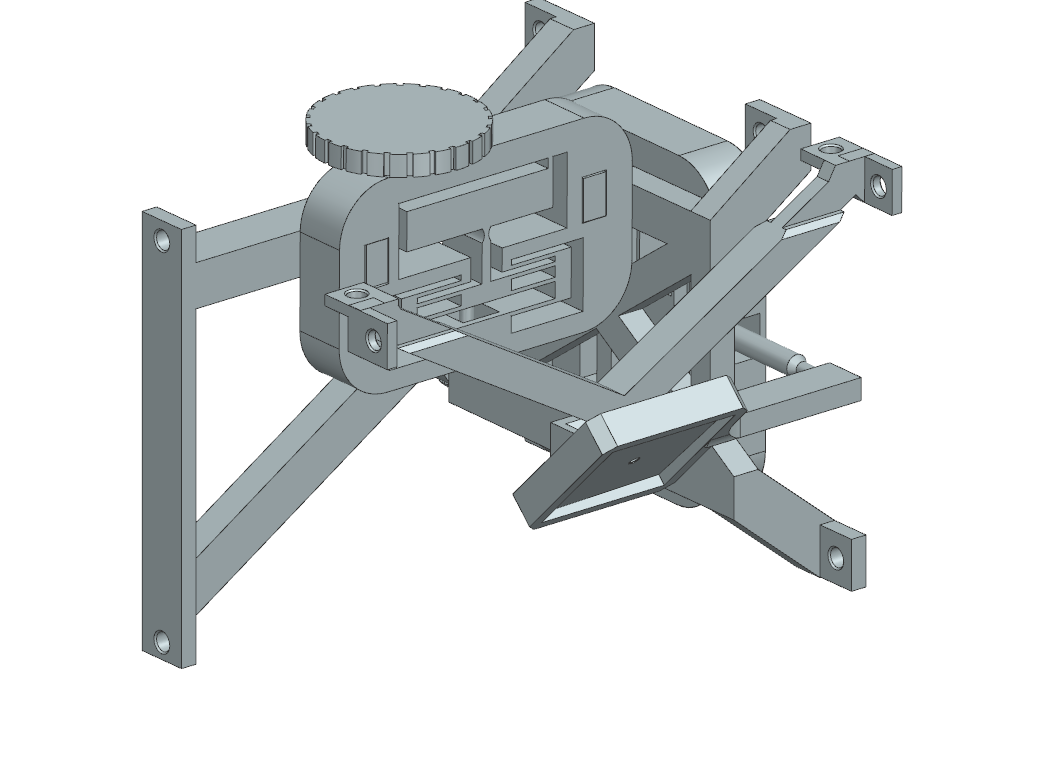
- Mirror Steering Mechanism (PKM) — Two flexure assemblies with transmission ratios, operated by bolts with dials for precise positioning. Dimensions: 101 mm x 80 mm x 106 mm
- Mirror Mount — Connects the mirror to the flexure output stages
Flexure Design
Flexures were chosen for the small displacements required, providing:
- Zero friction — no stick-slip or backlash
- No wear — monolithic elastic deformation
- Deterministic motion — compliant in desired DOFs, stiff in all others
The transmission ratio was designed to be very small, allowing large dial rotations to produce tiny mirror adjustments without reducing the total stroke. I iterated through several flexure topologies including notch flexures, toroidal flexures, and parallel guiding mechanisms before settling on a modular design that could be 3D printed and tested independently.
Design Iteration — My Personal Concepts
Before the team converged on the PKM, I explored three of my own actuation concepts and presented each to the group. All three center on the same primitive — a notch flexure cube, where four notch hinges in a monolithic block decouple X and Y tilt — but differ in how the operator drives it.
1. Notch flexure cube with internal screws
The base concept: a single compliant block with four notch flexures cut into the perimeter and two internal threaded bores. Turning each bolt deflects the cube along one principal axis; the orthogonal flexures keep the off-axis motion stiff. Compact and zero-parts, but the operator has to reach inside the structure to adjust it.
2. Beam-driven version
To get the adjustment screws out of the cube and into a more accessible location, I added two rigid beams that route torque from external knobs around a 90° corner and into the cube. This trades compactness for ergonomics — the operator now adjusts from the front face of the housing instead of reaching past the mirror.
3. String / wire-tensioned version
The third concept replaces rigid beams with tensioned wires. Each adjustment screw winds onto a small drum; turning the screw tightens one wire and loosens its antagonist, deflecting the cube along that axis. This decouples X and Y completely — each screw operates one axis with no cross-talk — at the cost of a preload step on assembly.
The team ultimately chose the PKM topology shown above, but the iteration through these three variants was where most of the precision-design intuition came from — the trade-off between compactness, operator ergonomics, and decoupling cleanly maps onto how each variant routes the adjustment input to the flexure.
After that down-selection, the production design used rigid beams with notch flexures, incorporating:
- Tongue-and-groove joints for assembly
- Rubber band preloading for backlash elimination
- Lever-based transmission for fine adjustment
Prototyping and Testing
The prototype was manufactured at TU/e's Innovation Space using:
- 3D printing (PLA, with careful attention to layer/fiber orientation for flexure fatigue life)
- Laser cutting for the structural panels
During testing, we identified 5 design shortcomings (toroidal flexure thickness, actuation rod stiffness, mounting rod length, hex nut dimensions, press-fit block sizing) and iterated on each. I also designed and built a custom wooden test rig from scratch when the initial test setup proved too compliant for meaningful measurements.
Results & Discussion
This project was my deepest dive into precision engineering. The gap between a CAD model and a working prototype is significant — 3D print fiber orientation affects flexure behavior, press-fit tolerances are unforgiving, and testing setups must be stiffer than the device under test. Learning to identify and fix shortcomings systematically was as valuable as the initial design work.
Technologies Used
Siemens NX (CAD), 3D printing (PLA), laser cutting, Innovation Space (TU/e), precision flexure design, exact constraint design principles