Overview
In this first-year Design-Based Learning project (4GA10, Q2 2022-2023) at TU Eindhoven, our team of 8 designed and built a launching mechanism to fire a projectile as far as possible. The mechanism was powered by falling M20 nuts (counterweights) that transfer energy through a drum and rope to a rotating club arm. All custom parts were 3D printed using SLS (Selective Laser Sintering) in Nylon 12.
Design Process
The project followed a structured 7-phase design methodology:
- Problem definition — Understand constraints (materials, budget, mechanism type)
- Concept generation — Brainstorm launcher types (trebuchet, whipper, catapult, club)
- Concept evaluation — Pugh matrix comparison on range, reliability, manufacturability
- Detailing — Full CAD in Siemens NX with dimensioned drawings
- Realization — SLS 3D printing, assembly, rope/counterweight integration
- Testing — Iterative firing tests with measurement
- Evaluation — Performance analysis and reflection
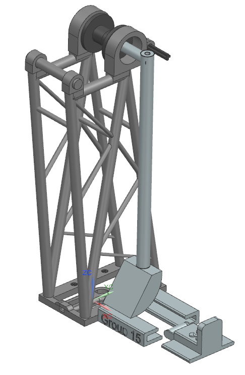
Mechanism Design
The final design uses a club-arm launcher — a rotating arm driven by a counterweight via a drum-and-rope system:
- Frame — SLS-printed Nylon 12 structure bolted to a base plate
- Club arm — Rotates on bearings, accelerated by falling counterweight
- Drum — Rope wraps around the drum, converting gravitational potential energy to rotational kinetic energy
- Sled and rails — Guides the projectile with graphite-coated rails for low friction
- Trigger mechanism — Pin-release system (redesigned after testing to reduce vibration)
Key Engineering Challenge
During first firing tests, the trigger pin required excessive force to pull because the club arm rested perpendicular to it, loading the pin with the full arm weight. We relocated the pin higher on the frame so the arm rests nearly vertical, reducing pull force and firing vibrations — and gaining extra potential energy from the higher starting position.
Results & Discussion
This was my first full design-build-test project at university. The most valuable lesson was that manufacturing reality always deviates from CAD — SLS print tolerances meant rails needed sanding, interference fits needed adjustment, and rope lengths needed empirical tuning. Learning to iterate quickly in the physical domain was as important as getting the design right on screen.
Technologies Used
Siemens NX (CAD), SLS 3D printing (Nylon 12), bearings, counterweight mechanics, LaTeX